Access control Connection diagram
Instructions
Wiring the Control Panel
Description:
The control panel is the central hub of the access control system, responsible for processing signals from readers and sensors, controlling door locks, and managing power distribution. Proper wiring of the control panel is crucial for the system to function correctly.
#### Wiring Instructions:
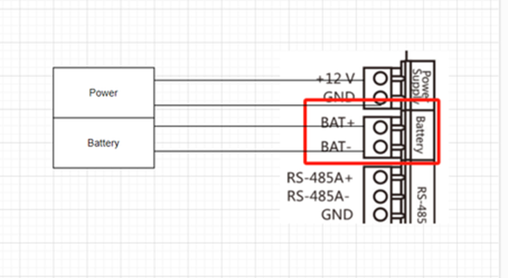
#### 1. Power Connection:
o Connect the power supply to the control panel’s power input terminals.
o Ensure the correct voltage is supplied (typically 12V or 24V DC, depending on the system specifications).
o If a backup battery is used, connect it to the battery terminals on the control panel.
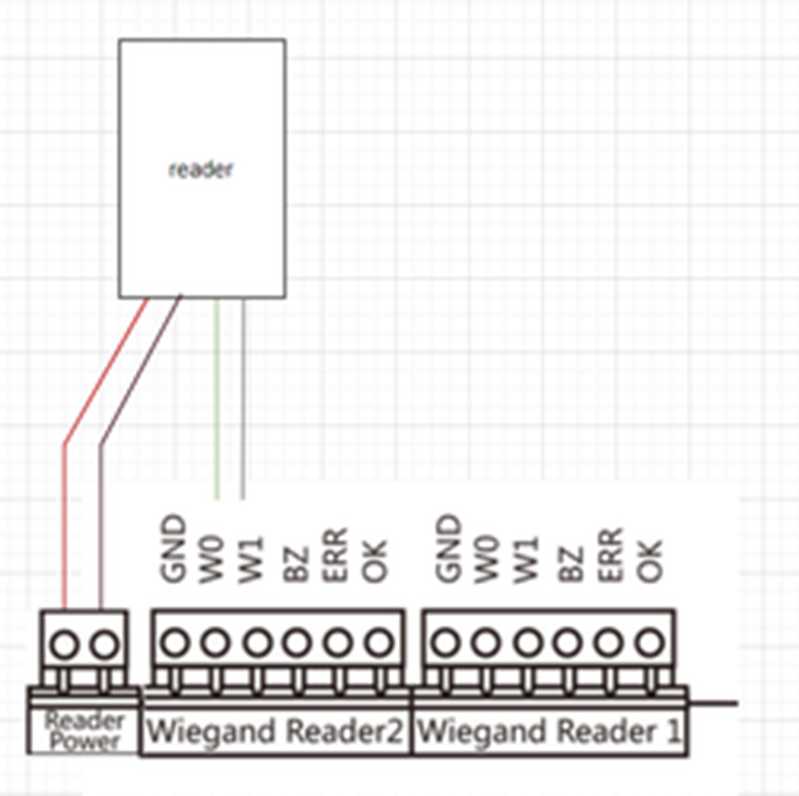
2. Reader Connections:
o Identify the terminals on the control panel for connecting readers (typically labeled as Wiegand Input or similar).
o Connect the reader wires according to the following:
- Red Wire (Power): Connect to the positive terminal (+12V or +24V).
- Black Wire (Ground): Connect to the ground terminal (GND).
- Green Wire (Data 0): Connect to the Data 0 (D0) terminal.
- White Wire (Data 1): Connect to the Data 1 (D1) terminal.
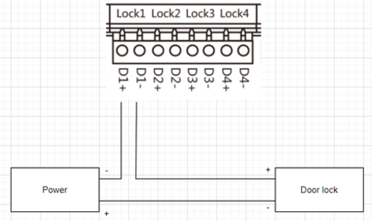
3. Door Lock Connection:
o Determine the lock type (e.g., magnetic lock or electric strike) and connect it to the corresponding terminals on the control panel.
o For a magnetic lock, connect the positive and ground wires to the “Lock” terminals.
o For an electric strike, connect the control wires to the “Strike” terminals.
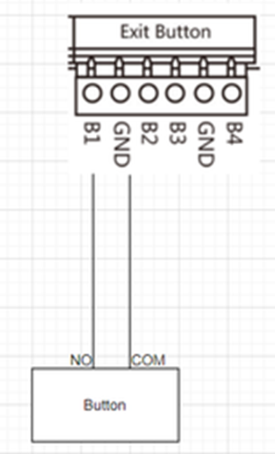
4. Exit Button Connection:
o Connect the exit button to the “Request to Exit” (REX) terminals on the control panel.
o The wiring typically involves connecting one terminal of the button to the REX input and the other to the ground (GND).
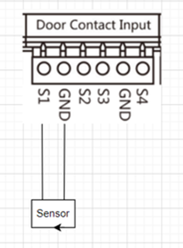
5. Sensor Connections:
o Connect door sensors (e.g., door position sensors) to the designated input terminals on the control panel.
o Wire the sensor to the “Door Status” input, usually using the NO (Normally Open) or NC (Normally Closed) terminals depending on the sensor type.
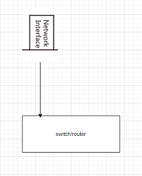
6. Network Connection (if applicable):
o Connect the control panel to the network using the Ethernet port.
o Ensure the control panel’s IP address is configured for communication with the monitoring software.
Wiring Diagram:
Here is an example diagram that visually represents the wiring instructions provided above.
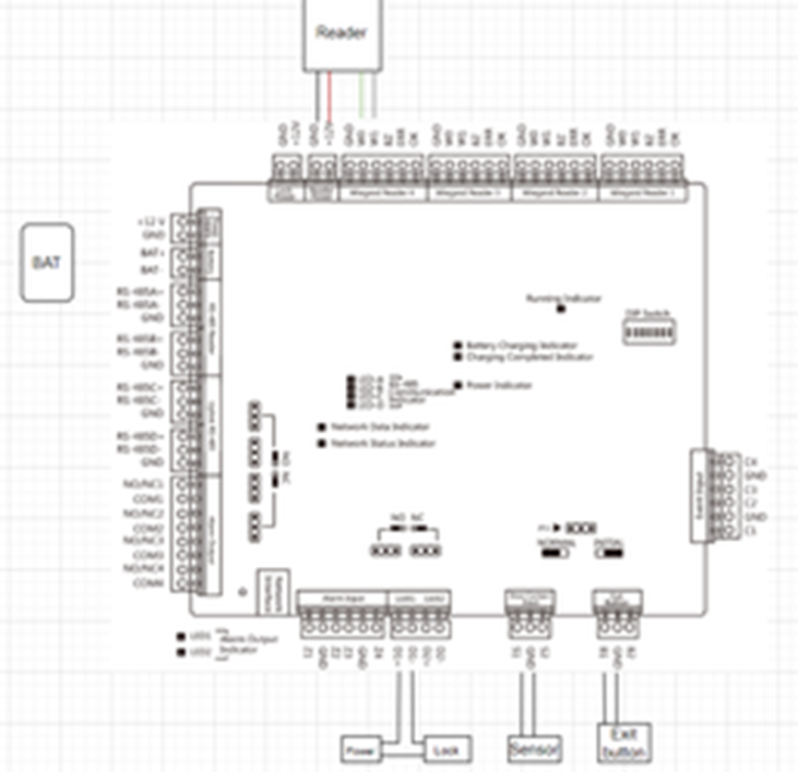
• Control Panel: Central rectangular block labeled “Control Panel.”
• Power Supply: A rectangular block labeled “Power Supply” connected to the “Power Input” terminals of the Control Panel.
• Readers: Two rectangles labeled “Reader 1” and “Reader 2” connected to the Wiegand Input terminals on the Control Panel. Use colored lines (Red, Black, Green, White) to represent wires.
• Door Lock: A block labeled “Magnetic Lock” connected to the “Lock” terminals of the Control Panel.
• Exit Button: A block labeled “Exit Button” connected to the “REX” terminals.
• Sensor: A block labeled “Door Sensor” connected to the “Door Status” terminals.
• Network Connection: A line from the Control Panel to a cloud icon labeled “Network” to represent Ethernet connection.