1. Safety Mandates and Field Precautions
The strategic implementation of safety protocols is the cornerstone of AIBASE-T-2P-314 field operations. These mandates are not suggestions; they are fundamental requirements to prevent catastrophic equipment failure, ensure personnel survival, and maintain the integrity of high-value components. Technical precision during the setup phase mitigates the risks of electrical arcing, mechanical collapse, and total asset loss.
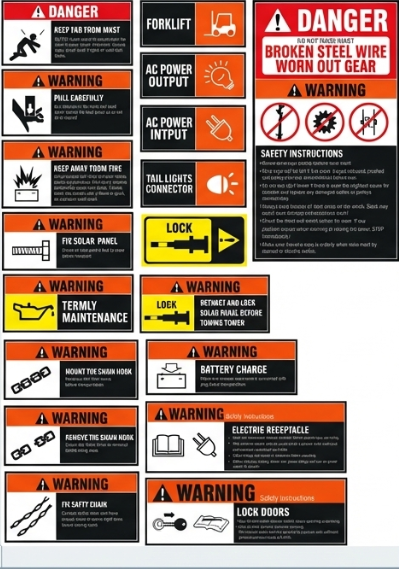
Critical Safety Alerts
Hazard Category | Specific Risks & Mitigations |
Electrical | DANGER: High-voltage DC circuits. Never take power directly from batteries. MANDATORY: Wear goggles and insulating gloves. NEVER unplug solar panel connectors while charging; this causes severe arcing, personal injury, and equipment damage. |
Mechanical | CRITICAL: Moving mast sections and winch cables. Keep personnel clear during operation. If winch cables develop slack or show signs of being worn/frayed, STOP IMMEDIATELY. Replace cables before proceeding. |
Environmental | STABILITY: High winds and uneven terrain. Lower the mast during storms. Ensure the unit is on a firm, level surface. Failure to do so negates the 72.7mph wind rating. |
Site-Specific Requirements
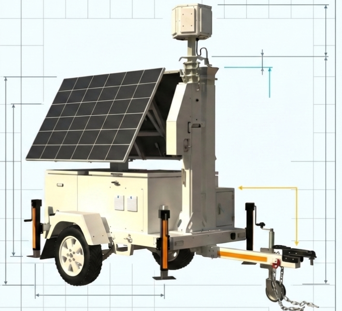
Technicians must execute a 360-degree site evaluation before deployment. The AIBASE-T-2P-314 mast extends to 24.6 ft (7.5m); verify a minimum overhead clearance of 25 ft to avoid lethal contact with power lines. MANDATORY: Secure the unit to a verified earthen ground using the grounding stud at the base of the mast. If the unit is equipped with a hydraulic mast, N46 anti-wear hydraulic oil must be replaced annually (first replacement at 3 months).
The "So What?" Layer: Failure to adhere to these mandates voids operational stability and risks catastrophic tipping. An ungrounded unit or damaged cable insulation risks energizing the trailer frame, turning the entire asset into a lethal electrocution hazard for any staff touching the chassis.
Once the site is verified safe and clear of obstructions, the technician must proceed to the physical stabilization of the unit.
--------------------------------------------------------------------------------
2. Physical Site Stabilization and Trailer Leveling
A firm, level foundation is the non-negotiable prerequisite for all telescopic and solar operations. Without a stabilized base, the mast cannot be extended without risking structural torque, and the solar array cannot be optimized. Proper leveling distributes the 900kg (1,980lb) weight evenly, protecting the internal components from misalignment.
Step-by-Step Stabilization Process
Initial Positioning: Use the Jockey Wheel to position the trailer on the flattest available ground.
Secure the Unit: Apply the manual hand brake and place the two provided wheel chocks firmly against the tires.
Deploy Outriggers: Pull the locking pins on the four manual outriggers and extend them fully. MANDATORY: Outriggers must remain extended at all times while the mast is elevated.
Level the Chassis: Observe the four integrated bubble levels. Rotate the jack handles clockwise to lower the jacks until they make firm contact with the ground.
Final Verification: Adjust until all four bubble levels are centered. Insert the safety locking pins into the outrigger handles immediately.
Impact of Surface Integrity
The 72.7mph (117kph) windproof rating is only valid on firm ground. If deployment on "soft shoulders" or loose soil is unavoidable, you MUST use auxiliary base plates or heavy plywood under the outrigger feet. Soft ground deployment without reinforcement voids the stability rating and risks unit shifting under load.
The "So What?" Layer: A correctly leveled unit ensures the mast remains perfectly vertical. A misaligned mast creates internal friction and structural stress, which leads to cable snapping or the mast "hanging up" during retraction, necessitating expensive field repairs.
With the trailer physically locked and leveled, the technician must proceed to the mechanical deployment of the PV panels.
--------------------------------------------------------------------------------
3. PV (Solar Panel) Deployment and Optimization
Solar orientation is the primary driver of system autonomy. The AIBASE-T-2P-314 features two 435W mono-crystalline panels that must be precisely angled and rotated to maximize kWh harvest. Even minor deviations can result in a power deficit that forces the backup generator to run prematurely.
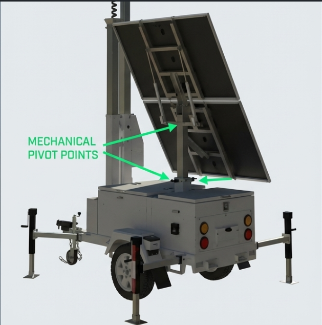
Mechanical Deployment Sequence
Panel Extension: Slide the PV panels out along their tracks to the fully extended position.
Angle Adjustment: Locate the internal cabinet switch (Label ⑩). Use the electric lift to raise the panels. MANDATORY: Hold the button down until the panels reach their maximum angle before fine-tuning.
Orientation: Pull the mast pins at the base of the solar bracket. Rotate the assembly to face the sun:
Northern Hemisphere: Face South.
Southern Hemisphere: Face North.
Locking: Re-insert the pins to secure the direction.
Geographic Angle Optimization
Location | Approximate Latitude | Optimal Baseline Angle (Year-Round) | Winter Adjustment Angle | Panel Orientation |
|---|---|---|---|---|
Toronto, ON | 43.65°N | ~44° | 50° - 60° | South |
Vancouver, BC | 49.3°N | ~49° | 50° - 60° | South |
Calgary, AB | 51.0°N | ~51° | 50° - 60° | South |
Halifax, NS | 44.6°N | ~45° | 50° - 60° | South |
The "So What?" Layer: Orientation precision is critical. According to the Power Consume Chart, a 120W load in winter (2.5 Peak Sun Hours) creates a 0.26 kWh daily deficit. A 15-degree variance in angle can collapse the "Days to Empty" from infinite to just 5.3 days, triggering a total system shutdown if the generator fails.
After the panels are optimized, the technician must execute the strict electrical power-on sequence.
--------------------------------------------------------------------------------
4. Electrical Integration and System Power-On Sequence
The order of operations is non-negotiable. The MPPT (Maximum Power Point Tracking) controller requires battery voltage detection to establish logic parameters before it can process solar power.
Strict Power-On Protocol
MANDATORY: Execute these steps in exact order or risk MPPT logic failure:
Battery Power Button: Activate the button on the LFP battery.
Battery Isolator: Turn the red isolator switch (Label ⑪) to "ON".
Battery Breaker: Switch the battery breaker (Label ⑤) to "ON".
PV Breaker: Switch the solar panel breaker (Label ⑤) to "ON".
Gasoline Generator Breaker: Switch the generator breaker (Label ⑤) to "ON".
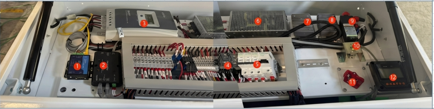
Cabinet Component Roles
① TCP306 (Remote Module): Enables remote monitoring of Battery/PV status.
② 1M2S (RS485 Splitter): Coordinates data communication for the controller.
③ MPPT: The "brain" managing charge/discharge logic.
⑥ 24V to 12V Converter: Powers 12V equipment (Positive 841, Negative 940).
⑦ 24V Voltage Stabilizer: CRITICAL: Protects sensitive NVR/IPCs from voltage spikes during generator start-up.
⑧ 24V to 48V Converter: Powers high-voltage equipment (Positive 811, Negative 910).
⑫ MT50: Local diagnostics display.
The "So What?" Layer: An out-of-order startup (e.g., PV before Battery) prevents the MPPT from reading battery status. This can cause the controller to default to incorrect voltage settings, leading to charging failure or permanent damage to the LFP battery bank.
--------------------------------------------------------------------------------
5. System Validation and Monitoring
Technicians must verify real-time data to confirm the unit is mission-ready. Use the MT50 display (Label ⑫) for all on-site diagnostics.
Local Display (MT50) Verification Checklist
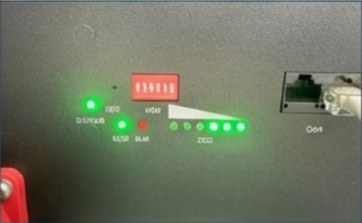
[ ] Battery Status: Icon must be solid (non-flashing), indicating recognition by the MPPT.
[ ] PV Voltage: Must read Minimum 30V. Readings below 30V or a flashing display indicate a PV fault.
[ ] Strobe Check: Turn on the strobe breaker. VERIFY: All 4 strobe lights (2 on the camera box, 2 on the trailer body) are flashing.
[ ] Grounding: Confirm the earthen ground connection is secure.
Generator Autonomous Thresholds
The Gasoline Generator is set for autonomous recovery based on the Battery State of Charge (SOC):
Auto-Start: 20% SOC.
Auto-Stop: 50% SOC.
The "So What?" Layer: Proactive monitoring of the MT50 prevents "Days to Empty" scenarios. By validating PV voltage and SOC thresholds, you ensure the backup generator—capable of providing 103 days of runtime for a 90W load—is ready to compensate for environmental harvest deficits.
--------------------------------------------------------------------------------
6. Maintenance and Seasonal Adjustments
Environmental factors like dust, snow, and bird droppings significantly degrade solar efficiency. Routine maintenance is the only way to ensure the 4000-cycle battery lifespan and system autonomy.
Mandatory Inspection Tasks
Daily: Clean PV panels and the Photocell with a soft cloth and mild detergent. Remove snow immediately.
Winch Cable: Inspect for slack or fraying daily. STOP if damage is found.
DANGER: NEVER operate the neutral gear bolt on an electric winch while the mast is extended. This will cause the mast to fall instantly, resulting in death or total equipment destruction.
Generator: Mandatory first oil/filter change after 20 hours of operation or 1 month. Annual maintenance thereafter.
Battery: Inspect terminals for corrosion annually. If storing long-term, turn off all breakers to prevent deep discharge.
The "So What?" Layer: Neglected maintenance transforms an autonomous asset into a high-liability failure. Dirty panels create a "No Sun" scenario, forcing the generator to run excessively, increasing fuel costs and mechanical wear, and eventually leading to a complete power loss.
Final Statement: The technician is the steward of the LT-MT2P's operational lifecycle. Final site sign-off is only authorized once the unit is level, powered in sequence, and the maintenance schedule is recorded.